
My Level 3 Certification Project
By Mark Clauson
Member -
I set off on this project originally to design and build a high altitude, minimal diameter, paper and wood constructed level 3 project. My original design was centered on a M1315 White Lightning 75mm Aerotech motor. If that sounds extreme to you, well it is. I like taking rocketry to the extreme. Who wants to see “just another M motor” launch when they can witness something extreme. After successfully building a paper and wood 3in diameter rocket that flew on a K270W slow burn to almost 13,000 feet, I was hooked. The long burn time of a slow burn white lightning is unlike anything I have experienced in my 20+ years of model, hobby, mid, and high power rocketry. I went back to the design and quickly realized that this rocket would be perfect for a slow burn M650 White Lightning Motor.
The design phase started with a LOC 75mm motor mount tube filled with a M650. I then wrapped 75mm to 98mm centering rings spaced just 6 inches apart. Around the centering rings I placed a LOC 98mm motor mount tube. At the fore end of the 98mm tube I fitted a 98mm to 75mm airframe reducer. All but the fins and motor retainer were now in place for the “booster section” of the rocket.
The “payload section” was to consist of an undetermined length of LOC 75mm motor mount tube (target size was just long enough to contain the main parachute and recovery system) that continuing up the rocket, couples to an electronics bay. Above the electronic bay is another undetermined length of LOC 75mm motor mount tube for the drogue chute, topped off with a Polecat 3” fiberglass 6:1 nosecone.
I then added the tail cone retainer and designed the fins to be thru-wall mounted touching the centering rings just fore and aft of the fins.
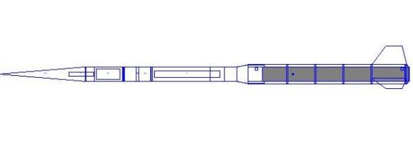

After “playing around” on the simulator for a while, I finalized my design. You can download a copy of my Rocksim file here. This rocket will reach Mach1 at approx 2.9 seconds from ignition at 1700 feet. It will reach a maximum velocity of Mach 1.49 and eventually return sub-sonic at 11.1 seconds at an altitude of 13,000 feet. It will come to a coasting stop at apogee altitude of 22,000 – 23,000ft. I have designed the rocket to fall back to earth under drogue chute at a rate of 45 feet per second. The Main chute will deploy at 1000 feet and slow the rocket to approximately 17 feet per second. I decided that I had the design phase finished and it was now time to move forward. I ordered the components I would need. After they arrived at the house, it was time to get busy building.
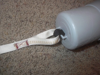
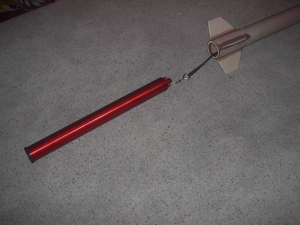
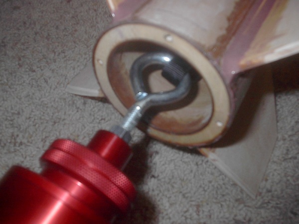
The Construction phase started with the motor mount tube. First I removed the exterior glassine layer. Then I fitted 4 centering ring around it starting 7½ inches from the aft edge of the tube and then the subsequent 3 spaced 6 inches apart moving forward. I then coated the entire motor mount tube (except for the fin area) with epoxy to add strength to the tube. I have chosen to utilize only West System Epoxy and additives for this build. Next I added epoxy gussets to every centering ring fore and aft. I then designed a way to sandwich the four aft retainer ring nuts in between the two aft centering rings creating an aft centering ring that was now ½ inch thick. I then hollowed out the aft end of the 4” to 3” airframe reducer leaving enough material to create another centering ring out of the aft end of the reducer. Next I cut a slit in the top of the airframe reducer just large enough to pass the motor casing safety strap thru. I roughed up the gluing surfaces to assure better adhesion, and attached the tubular nylon to the airframe reducer. The airframe reducer now looked like this;

I then cut the body tube fin slots out of the 4” LOC motor mount tube material. I used the LOC motor mount tubing because of the added thickness and the extra structural strength it would provide. I test fit the motor tube in the exterior body tube, assuring that the fin slots and centering rings all lined up properly as well as the air frame reducer.
Next I cut, sanded to size, and knife edged the fins. I then used epoxy to cement the motor mount tube inside the 4” body tube. Next I tacked the fins into place assuring the proper 90 degree angle between each fin. The next step was to apply interior fillets to the fins using only the finest Epoxy mixed with the strongest filleting additive to achieve the strongest possible bond. Filleting the fins to both the exterior of the motor tube and the interior wall of the body tube, coupled with the later exterior fillets, would give each fin SIX fillets in all. Let me just tell you, these fins are not coming out! Then I glued the aft centering ring into place assuring the aft motor retainer ring nuts fell right in the middle of the fins. The rocket now looked like this;

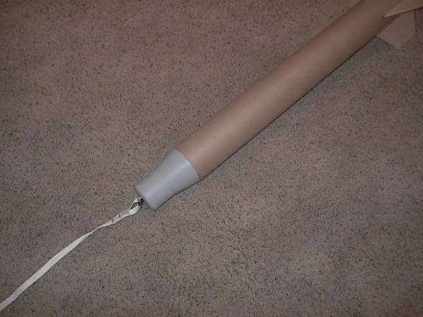
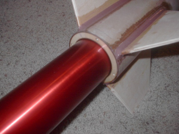
I then glued the airframe reducer, using epoxy, into the main body tube and around the motor mount tube forward end. The rocket “booster section” was now starting to take shape;


Ok, enough playing (for now). Let’s lay some peanut butter. That is a little term we use for the West system epoxy mixed with an additive, or additives, to thicken the epoxy to a state similar to peanut butter. Very thick and you have to be careful to shape the fillet’s properly. You do not want to sand these when they are dry. They are way too hard. It will literally tear the sand paper.


Ok, time to get back
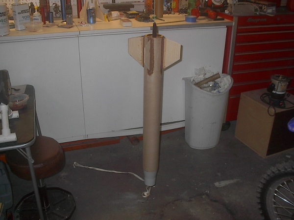
to assembly. The next thing I did was to
attach the Main Chute payload tube section. I used one tube coupler inside the tube right at the top of the
transition for added strength at the transition. I attached an extra long tube here so I could
cut it down to length with the Main Parachute and Shock Cord actually in place
(I wanted to keep waited space to an absolute minimum). The Rocket now looked like this:


Assemble and Inspect Rocket Components
and Documents
o
Rocket
o
Motor
retainer, Allen screws, and Allen wrench
o
Main
recovery system including Nomex pad (main parachute)
o
Drogue
recovery system including Nomex pad (drogue parachute
and streamer)
o
Shear
pins
o
Primary
altimeter and new 9V battery
o
Secondary
altimeter and new 9V battery
o
Rocket Hunter
transmitter and battery
o
Ejection
components (electric matches, black powder, masking tape)
o
Motor casing
o
Motor and lithium
grease
o
Igniter
o
Flight card
o
Tripoli
Certification form
o
TAP pre-flight
data capture form
o
Rocket drawing
o
Parts list
o
Electronics bay
wiring diagram
Pack Main Recovery System
o
Check position of
quick links and Nomex parachute pad
o
Attach shock cord
to motor casing safety strap using a quick link
o
Have other end of
main recovery system available for later attachment to electronics bay using a
quick link
o
Attach main
parachute to shock chord using a quick link
o
Pack recovery
apparatus inside airframe
Pack Drogue Recovery System
o
Check position of
quick links and Nomex parachute pad
o
Attach shock cord
to nose cone eye bolt using a quick link
o
Have other end of
drogue recovery system available for later attachment to electronics bay using
a quick link
o
Attach drogue
streamer and parachute to shock chord using a quick link
o
Pack recovery
apparatus inside nosecone and airframe
o
Remove aft bulk
plate, then remove electronics bay sled
o
Install primary
altimeter (PerfectFlight Hi-Alt)
o
Check battery and
replace as needed
o
Connect battery
and secure in bracket
o
Attach exterior
junction block leads
o
Check jumper settings for deployment of main chute at 1,000’(JP1-on JP2-off), and mach
delay of 12 seconds (JP3-on JP4-on)
o
Check altimeter
function, then ensure switch is in off position
o
Install secondary
altimeter (PerfectFlight Hi-Alt)
o
Check battery and
replace as needed
o
Connect battery
and secure in bracket
o
Attach exterior
junction block leads
o
Check jumper settings for deployment of main chute at 1,000’(JP1-on JP2-off), and mach
delay of 12 seconds (JP3-on JP4-on)
o
Check
altimeter function, then ensure switch is in off position
o
Slide
altimeter sled into the electronics bay
o
Test battery,
insert battery, and attach Rocket Hunter transmitter in electronics bay with
antenna sticking out of the drogue side of the bay
o
Test function of
Rocket Hunter
Assemble and Load Motor
o
Apply lithium
grease on threads of casing forward and aft closures
o
Assemble motor
per instructions
o
Attach motor
safety strap to forward enclosure
o
Slide
motor into motor tube and secure with motor retainer
o
Prepare igniter
and wrap around rocket body near fins
Ejection Charge Assembly
o
Clear people from immediate area
o
Prepare
two ejection charges with dual electric matches
§
3 – 3.5
grams of FFFFG black powder for main parachute
§
3 –
3.5 grams of FFFFG black powder for drogue parachute
o
Place
ejection charges in main ejection canisters, cover canisters with masking tape,
cut electric match wire to length, strip ends, and attach electric match leads
to junction blocks for charges (“M1” and “M2”)
o
Place
ejection charges in drogue ejection canisters, cover canisters with masking
tape, cut electric match wire to length, strip ends, and attach electric match
leads to junction blocks for charges (“D1” and “D2”)
o
Activate Rocket
Hunter
o
Test function of
Rocket Hunter
o
Attach the main
recovery system to the electronics bay eye bolt using a quick link
o
Install the
electronics bay into the main chute side of the rocket and using the alignment marks, and attach with shear pins
o
Attach the drogue
recovery system to the electronics bay eye bolt using a quick link
o
Install the
drogue payload section with recovery system and nosecone to the electronics bay
and rest of the rocket
Check-In
o
Fill
out flight card
o
Weigh
rocket (add info to flight card)
o
Provide
pre-flight data capture form to TAP committee members
o
Check
in with RSO for inspection and pad assignment
o
Have
multi-form certification form available for RSO
o
Have
Pre-Flight Data Capture Form and package available for RSO
Launch Pad Procedures
o
Load rocket on
rail
o
Secure rail in
vertical position
o
Insert igniter
and secure in position
o
Test launch leads
to make sure there is no power, then attach leads to igniter and ensure they
are not touching
o
Arm altimeters
and confirm state of readiness from beeps
o
Photograph rocket
on pad
o
Ensure that
flight witness(es) (TAPs) are in place and ready for
launch
o
Abort launch if either
altimeter signals a problem
o
Disarm both
altimeters
o
Remove igniter
o
Remove rocket
from pad
o
Cut wires to
ejection charges
o
Take rocket back
to flight line
Misfire Procedure
o
Prepare a new
igniter
o
Remove failed
igniter
o
Insert new
igniter and secure in position
o
Attach leads to
igniter and ensure they are not touching
o
Follow the
“abort” procedures above if necessary
Launch Observation and Recovery
Preparation
o
Ensure that
flight witnesses are in place and ready for launch
o
Ensure photographers are in place to photograph
launch
o
Carry a recovery
tool set and water
o
Multi-bit
screwdriver
o
Wire cutters
o
Needle-nose
pliers
o
Paper and pencil
o
Small backpack
o
Activate
the Rocket Hunter receiver and check function
CLEAR SKYS?
5,4,3,2,1…..LAUNCH
Recovery/Post-Flight Checklist
Normal Post Flight Recovery
o
Turn off power to
altimeters
o
Safe ejection
circuits by cutting the four electric match wires
o
Turn-off the Rocket Hunter
o
Remove any
non-discharged ejection charges
o
Record PerfectFlight Hi-Alt 1 altimeter altitude data
o
Record PerfectFlight Hi-Alt 2 altimeter altitude data
o
Gather and repack
recovery components and re-assemble rocket for return to launch area
o
Remove
motor casing and discard remnants of spent motor
o
Remove
and store altimeters
Flight Failure Checklist
o
Follow same
procedure for “Normal Post Flight Recovery”
